3軸加速度センサーとは
3軸加速度センサーはXYZ軸の加速度を測定できるセンサーである。携帯電話やゲームのコントローラ、PCの落下検知、ロボットの姿勢制御に用いられている。地磁気センサと合わせることで電子コンパスとして機能することが可能で、GPS(全地球測位網)と連携した様々なサービスがある。
下図は、iPhoneに実装されている3軸加速度センサー(参照元)。
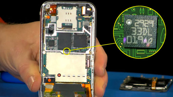
3軸加速度センサーはXYZ軸の加速度を測定できるセンサーである。携帯電話やゲームのコントローラ、PCの落下検知、ロボットの姿勢制御に用いられている。地磁気センサと合わせることで電子コンパスとして機能することが可能で、GPS(全地球測位網)と連携した様々なサービスがある。
下図は、iPhoneに実装されている3軸加速度センサー(参照元)。
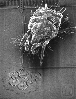
3軸加速度センサーは、MEMS(Micro Electro Mechanical Systems)という技術によって実現されている。MEMSは超小型の機械構造を作り出し電子回路と組み合わせることができる最新の技術で、このMEMSにより様々なセンサーやアクチュエータが開発されている。
下図は、MEMSで実現したダニより小さなギア。
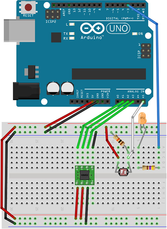
前回の講義ノート「Arduino+CdS」から続けて以下の部品を追加実装する。
・3軸加速度センサーKXR94-2050 or KXM52-1050
・ジャンパ線 赤3本、黒3本、緑3本
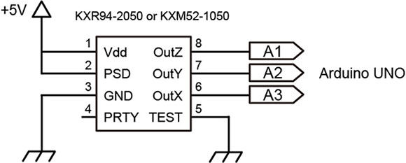
2番ピンは、KXM52-1050ではPower Shut Down、KXR94-2050ではEnableと名前が異なるが、機能は同じでVddに接続する。GNDに接続するとスタンバイモードになる。切り替えることで節電させることができるものだが、ここでは常にVddに接続する。
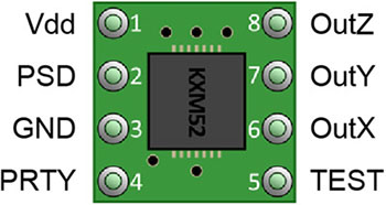
3軸加速度センサーの向きに注意して取り付ける。
加速度センサーのアナログ値をシリアル通信を使ってProcessingに送信してグラフとして視覚化する。
ArduinoとProcessingのプログラムを同時に利用するので注意。
空のスケッチを作成して、以下のコードをコピー&ペースト後、スケッチを保存する。
// 加速度をProcessginで視覚化(Arduino側)
// 2017.12 nakayasu

int sensorValue[3];
int outputValue[3];
int inByte; // 受信データ

void setup()
{
  for(int k=0; k < 3; k++){ sensorValue[k] = 0; outputValue[k] = 0; } Serial.begin(9600); establishContact(); // シリアル通信確立用 } void loop() { if (Serial.available() > 0) {
    inByte = Serial.read(); //シリアル受信
    sensorValue[0] = analogRead(1); //A1ピン入力 - Z(KXM52-1050の8pin)
    delay(10);
    sensorValue[1] = analogRead(2); //A2ピン入力 - Y(KXM52-1050の7pin)
    delay(10);
    sensorValue[2] = analogRead(3); //A3ピン入力 - X(KXM52-1050の6pin)
    delay(10);
    // センサー値をシリアル通信用に10bit(0〜1023)から8bitへ(0〜255)変換する
    outputValue[0] = map(sensorValue[0], 0, 1023, 0, 255);
    outputValue[1] = map(sensorValue[1], 0, 1023, 0, 255);
    outputValue[2] = map(sensorValue[2], 0, 1023, 0, 255);
    // シリアル送信
    Serial.write(outputValue[0]);
    Serial.write(outputValue[1]);
    Serial.write(outputValue[2]);
  }
}

void establishContact() { // シリアル通信が確立されるまでAを送信し続ける
  while (Serial.available() <= 0) {
    Serial.print('A');
    delay(300);
  }
}
スケッチデータのダウンロード
コンパイル、書き込みを行う。Arduinoにプログラムを書き込んだ時点ではシリアル通信がスタートしない。Processingを起動して送信側と受信側でスタートデータの送受信が完了してはじめてシリアル通信がスタートする。
空のスケッチを作成して、以下のコードをコピー&ペースト後、スケッチを保存する。
// 加速度をProcessginで視覚化(Processing側)
// 2017.12 nakayasu

import processing.serial.*; // シリアルライブラリの読み込み
Serial myPort;
int[] serialInArray = new int[3];
int serialCount = 0;
int[] xvals;
int[] yvals;
int[] zvals;
int a0 = -1000;
int a1 = -1000;
int a2 = -1000;
boolean firstContact = false;

void setup()
{
  size(600, 400);
  xvals = new int[width];
  yvals = new int[width];
  zvals = new int[width];
  for(int i=1; i < width; i++) {
    xvals[i] = -300;
    yvals[i] = -200;
    zvals[i] = -200;
  }
  printArray(Serial.list()); // コンソールにシリアルデバイスの表示
  String portName = Serial.list()[3]; //シリアルデバイスナンバー
  myPort = new Serial(this, portName, 9600);
}

void draw()
{
  background(0);
  stroke(60);
  line(0, height/6, width, height/6);
  line(0, 3*height/6, width, 3*height/6);
  line(0, 5*height/6, width, 5*height/6);

  for(int i=1; i < width; i++) {
    xvals[i-1] = xvals[i];
    yvals[i-1] = yvals[i];
    zvals[i-1] = zvals[i];
  }
  // Add the new values to the end of the array
  xvals[width-1] = a2; //X A3 to 6pin on KXM52-1050
  yvals[width-1] = a1; //Y A2 to 7pin on KXM52-1050
  zvals[width-1] = a0; //Z A1 to 8pin on KXM52-1050

  for(int i=1; i < width; i++) { stroke(0, 180,255); point(i, xvals[i]-58); stroke(255, 20,0); point(i, yvals[i]+73); stroke(0, 255,0); point(i, zvals[i]+142); } fill(0, 180,255); text("X: " + a2, 10, 15); fill(255, 20, 0); text("Y: " + a1, 10, 15 + height/3); fill(0, 255, 0); text("Z: " + a0, 10, 15+2* height/3); } void serialEvent(Serial myPort) { int inByte = myPort.read(); if (firstContact == false) { if (inByte == 'A') { myPort.clear(); // clear the serial port buffer firstContact = true; // you've had first contact from the microcontroller myPort.write('A'); // ask for more } } else { // Add the latest byte from the serial port to array: serialInArray[serialCount] = inByte; serialCount++; if (serialCount > 2 ) {
      a0 = serialInArray[0];
      a1 = serialInArray[1];
      a2 = serialInArray[2];
      myPort.write('A'); // Send a capital A to request new sensor readings:
      serialCount = 0; // Reset serialCount:
    }
  }
}
スケッチデータのダウンロード
XYZの加速度の電圧値がグラフで表示される。Arduinoのアクリルボード自体を上下左右に動かすことでどの方向がXYZに対応しているかが理解できる。
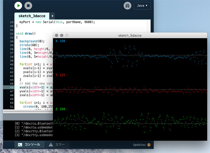
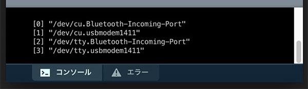
環境により15行目のシリアルデバイスナンバー([]内の数字)を変更する必要がある。シリアルデバイスナンバーは下図のようにProcessingのコンソールウィンドウ上で確認できる。/dev/tty.usbmodem****の表記のものがArduino。
Arduinoのスケッチは「4.加速度をProcessginで視覚化」と同じものを利用する。
空のスケッチを作成して、以下のコードをコピー&ペースト後、スケッチを保存する。
// Cubeを揺らす(加速度値)(Processing側)
// 2017.12 nakayasu

import processing.serial.*; // シリアルライブラリの読み込み
Serial myPort;
int[] serialInArray = new int[3];
int serialCount = 0;
int a0, a1, a2;
boolean firstContact = false;

void setup()
{
  size(640, 480, P3D);
  noStroke();
  colorMode(RGB, 1);
  printArray(Serial.list()); // コンソールにシリアルデバイスの表示
  String portName = Serial.list()[3]; //シリアルデバイスナンバー
  myPort = new Serial(this, portName, 9600);
}

void draw()
{
  background(0);
  translate(width/2+(a2-127)*4, height/2+(a0-190)*4, (a1-127)*-8);
  rotateX(1); rotateZ(1);
  scale(100);
  beginShape(QUADS);
  fill(0, 1, 1); vertex(-1, 1, 1); fill(1, 1, 1); vertex( 1, 1, 1);
  fill(1, 0, 1); vertex( 1, -1, 1); fill(0, 0, 1); vertex(-1, -1, 1);

  fill(1, 1, 1); vertex( 1, 1, 1); fill(1, 1, 0); vertex( 1, 1, -1);
  fill(1, 0, 0); vertex( 1, -1, -1); fill(1, 0, 1); vertex( 1, -1, 1);

  fill(1, 1, 0); vertex( 1, 1, -1); fill(0, 1, 0); vertex(-1, 1, -1);
  fill(0, 0, 0); vertex(-1, -1, -1); fill(1, 0, 0); vertex( 1, -1, -1);

  fill(0, 1, 0); vertex(-1, 1, -1); fill(0, 1, 1); vertex(-1, 1, 1);
  fill(0, 0, 1); vertex(-1, -1, 1); fill(0, 0, 0); vertex(-1, -1, -1);

  fill(0, 1, 0); vertex(-1, 1, -1); fill(1, 1, 0); vertex( 1, 1, -1);
  fill(1, 1, 1); vertex( 1, 1, 1); fill(0, 1, 1); vertex(-1, 1, 1);

  fill(0, 0, 0); vertex(-1, -1, -1); fill(1, 0, 0); vertex( 1, -1, -1);
  fill(1, 0, 1); vertex( 1, -1, 1); fill(0, 0, 1); vertex(-1, -1, 1);
  endShape();
}

void serialEvent(Serial myPort) {
  int inByte = myPort.read();
  if (firstContact == false) {
    if (inByte == 'A') {
      myPort.clear(); // clear the serial port buffer
      firstContact = true; // you've had first contact from the microcontroller
      myPort.write('A'); // ask for more
    }
  } else {
    // Add the latest byte from the serial port to array:
    serialInArray[serialCount] = inByte;
    serialCount++;
    if (serialCount > 2 ) {
      a0 = serialInArray[0];
      a1 = serialInArray[1];
      a2 = serialInArray[2];
      myPort.write('A'); // Send a capital A to request new sensor readings:
      serialCount = 0; // Reset serialCount:
    }
  }
}
スケッチデータのダウンロード
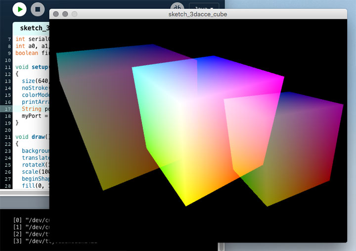
Arduinoのアクリルボードを上下左右に動かすことでCubeが揺れる。
加速度値から傾斜角度を算出してProcessingに送信、Cubeの回転角度として利用する。
空のスケッチを作成して、以下のコードをコピー&ペースト後、スケッチを保存する。
// Cubeの回転(角度値)(Arduino側)
// 2017.12 nakayasu

int sensorValue[3];
int inByte; // 受信データ

void setup()
{
  for(int k=0; k < 3; k++) sensorValue[k] = 0;
  Serial.begin(9600); establishContact(); // シリアル通信確立用
}
void loop() {
  if (Serial.available() > 0) {
    inByte = Serial.read(); //シリアル受信
    sensorValue[0] = analogRead(1); //A1ピン入力 - Z(KXM52-1050の8pin)
    delay(10);
    sensorValue[1] = analogRead(2); //A2ピン入力 - Y(KXM52-1050の7pin)
    delay(10);
    sensorValue[2] = analogRead(3); //A3ピン入力 - X(KXM52-1050の6pin)
    delay(10);

    //センサー値を-1から1までの範囲にスケーリングしてsinθの値とする
    float xAxisSinTheta = mapInFloat(sensorValue[2], 306, 716, -1, 1);
    float yAxisSinTheta = mapInFloat(sensorValue[1], 306, 716, -1, 1);
    //値を-1から1までの範囲に制限
    xAxisSinTheta = constrain(xAxisSinTheta,-1,1);
    yAxisSinTheta = constrain(yAxisSinTheta,-1,1);
    //逆サインのラジアンを度に変換する
    int xAxisTilt = float(asin(xAxisSinTheta) * 180 / PI );
    int yAxisTilt = float(asin(yAxisSinTheta) * 180 / PI );
    // シリアル送信
    Serial.write(xAxisTilt);
    Serial.write(yAxisTilt);
  }
}

void establishContact() { // シリアル通信が確立されるまでAを送信し続ける
  while (Serial.available() <= 0) {
    Serial.print('A');
    delay(300);
  }
}

float mapInFloat(float x, float iMin, float iMax, float oMin, float oMax) {
  return (x - iMin) * (oMax - oMin) / (iMax - iMin) + oMin;
}
スケッチデータのダウンロード
コンパイル、書き込みを行う。Arduinoにプログラムを書き込んだ時点ではシリアル通信がスタートしない。Processingを起動して送信側と受信側でスタートデータの送受信が完了してはじめてシリアル通信がスタートする。
空のスケッチを作成して、以下のコードをコピー&ペースト後、スケッチを保存する。
// Cubeの回転(角度値)(Processing側)
// 2017.12 nakayasu

import processing.serial.*; // シリアルライブラリの読み込み
Serial myPort;
int[] serialInArray = new int[2];
int serialCount = 0;
int xangle, yangle;
boolean firstContact = false;

void setup()
{
  size(640, 480, P3D);
  noStroke();
  colorMode(RGB, 1);
  printArray(Serial.list()); // コンソールにシリアルデバイスの表示
  String portName = Serial.list()[3]; //シリアルデバイスナンバー
  myPort = new Serial(this, portName, 9600);
}

void draw()
{
  background(0);
  translate(width/2, height/2, -30);
  rotateX(radians(-30+360*xangle/255));
  rotateZ(radians(-360*yangle/255));
  scale(100);
  beginShape(QUADS);
  fill(0, 1, 1); vertex(-1, 1, 1); fill(1, 1, 1); vertex( 1, 1, 1);
  fill(1, 0, 1); vertex( 1, -1, 1); fill(0, 0, 1); vertex(-1, -1, 1);

  fill(1, 1, 1); vertex( 1, 1, 1); fill(1, 1, 0); vertex( 1, 1, -1);
  fill(1, 0, 0); vertex( 1, -1, -1); fill(1, 0, 1); vertex( 1, -1, 1);

  fill(1, 1, 0); vertex( 1, 1, -1); fill(0, 1, 0); vertex(-1, 1, -1);
  fill(0, 0, 0); vertex(-1, -1, -1); fill(1, 0, 0); vertex( 1, -1, -1);

  fill(0, 1, 0); vertex(-1, 1, -1); fill(0, 1, 1); vertex(-1, 1, 1);
  fill(0, 0, 1); vertex(-1, -1, 1); fill(0, 0, 0); vertex(-1, -1, -1);

  fill(0, 1, 0); vertex(-1, 1, -1); fill(1, 1, 0); vertex( 1, 1, -1);
  fill(1, 1, 1); vertex( 1, 1, 1); fill(0, 1, 1); vertex(-1, 1, 1);

  fill(0, 0, 0); vertex(-1, -1, -1); fill(1, 0, 0); vertex( 1, -1, -1);
  fill(1, 0, 1); vertex( 1, -1, 1); fill(0, 0, 1); vertex(-1, -1, 1);
  endShape();
}

void serialEvent(Serial myPort) {
  int inByte = myPort.read();
  if (firstContact == false) {
    if (inByte == 'A') {
      myPort.clear(); // clear the serial port buffer
      firstContact = true; // you've had first contact from the microcontroller
      myPort.write('A'); // ask for more
    }
  } else {
    // Add the latest byte from the serial port to array:
    serialInArray[serialCount] = inByte;
    serialCount++;
    if (serialCount > 1 ) {
      xangle = serialInArray[0];
      yangle = serialInArray[1];
      myPort.write('A'); // Send a capital A to request new sensor readings:
      serialCount = 0; // Reset serialCount:
    }
  }
}
スケッチデータのダウンロード
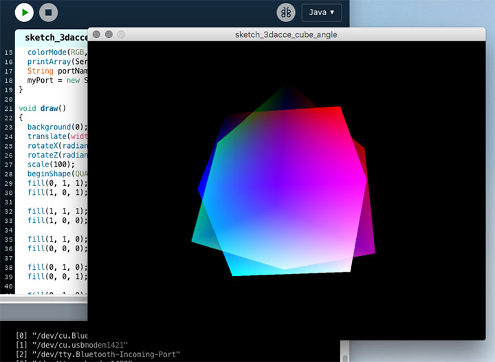
Arduinoのアクリルボードを傾けることでCubeが回転する。
Arduinoのスケッチは「6.Cubeの回転(角度値)」と同じものを利用する。
空のスケッチを作成して、以下のコードをコピー&ペースト後、スケッチを保存する。
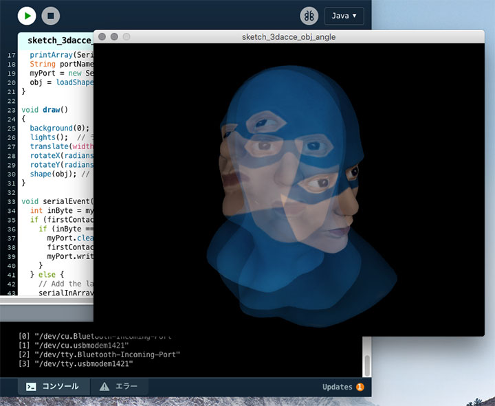
// 3Dモデルの回転(角度値)(Processing側)
// 2017.12 nakayasu

import processing.serial.*; // シリアルライブラリの読み込み
Serial myPort;
int[] serialInArray = new int[2];
int serialCount = 0;
int xangle, yangle;
boolean firstContact = false;
PShape obj;

void setup()
{
  size(640, 480, P3D);
  noStroke();
  colorMode(RGB);
  printArray(Serial.list()); // コンソールにシリアルデバイスの表示
  String portName = Serial.list()[3]; // シリアルデバイスナンバー
  myPort = new Serial(this, portName, 9600);
  obj = loadShape("captain_blender.obj"); // 3Dオブジェクトデータの読み込み
}

void draw()
{
  background(0);
  lights();  // ライトの追加
  translate(width/2, height/2-30, 100); // 位置調整
  rotateX(radians(175+360*xangle/255)); // 回転角度
  rotateY(radians(-180+360*yangle/255)); // 回転角度
  shape(obj); // 3Dデータの表示
}

void serialEvent(Serial myPort) {
  int inByte = myPort.read();
  if (firstContact == false) {
    if (inByte == 'A') {
      myPort.clear(); // clear the serial port buffer
      firstContact = true; // you've had first contact from the microcontroller
      myPort.write('A'); // ask for more
    }
  } else {
    // Add the latest byte from the serial port to array:
    serialInArray[serialCount] = inByte;
    serialCount++;
    if (serialCount > 1 ) {
      xangle = serialInArray[0];
      yangle = serialInArray[1];
      myPort.write('A'); // Send a capital A to request new sensor readings:
      serialCount = 0; // Reset serialCount:
    }
  }
}
スケッチデータのダウンロード
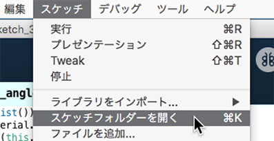
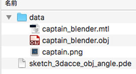
スケッチメニュー>スケッチフォルダーを開く。
dataフォルダを作成して以下の3つのデータ(captain_password.zip パスワードあり)を入れる。
・captain_blender.mtl
・captain_blender.obj
・captain.png
Arduinoのアクリルボードを回転することでキャプテンが回転する。